
Electro-mechanico-magic!
- Sundry Fires In Rain
- Feb 11, 2019
- 19 min read
Updated: Jun 4, 2025
THE DESIGN LAB
Research Question (RQ): How does increasing the number of turns of insulated copper wire around a ferromagnetic core affect the strength of an electromagnet, as measured by the number of safety pins it can attract?
Background information:
Electromagnets are devices that generate magnetic fields through the flow of electric current in a coil of wire, typically wound around a ferromagnetic core such as an iron nail.
The strength of the magnetic field produced by an electromagnet depends on several factors, including the number of turns of wire (N), the electric current (I), the material of the core, and the dimensions of the coil. For a solenoid (a long, cylindrical coil of wire), the magnetic field inside is B = μ0 n I , which shows that increasing the number of turns per unit length (n) directly increases the magnetic field strength (B), assuming the current (I) remains constant. Note that is the permeability of free space & is the number of turns per unit length.
Another way to express magnetic strength is H = N I / L , where H is the magnetic field in ampere-turns per metre (At/m), and L is the length of the coil in metres. This supports the idea that a greater number of wire turns creates a stronger electromagnet. The more turns you add, the longer the coil becomes, increasing the length of current-carrying conductor, and thus intensifying the magnetic field.
Hypothesis :
The strength of an electromagnet is not permanent and depends on the number of wire turns around the iron core. When electric current flows through the wire, a magnetic field is generated. Wrapping more coils increases the number of magnetic field lines, and these add together, strengthening the overall field. Magnetic field strength increases as more loops of wire are added to a solenoid, since each turn contributes to the total field within the core. According to Ampere’s Law, this strength is directly proportional to the number of wire turns per unit length. Thus, increasing the number of turns strengthens the electromagnet, which can be observed by a greater number of safety pins being attracted.
Apparatus :
· 1 × 9V DC battery
· 1 × Stopwatch or timer
· 1 × Ferromagnetic core (iron nail, 15 cm / 6 inches long)
· 6 × Identical safety pins
· 3 ft of 22-gauge insulated copper wire (enough for turns of 20, 30, 40, 50, and 60)
· 1 × Pair of small wire strippers
· 1 × Pair of gloves (for safety against heat)
· 1 × Cutting plier
· Tape (for securing loose wire ends if needed)
Procedure
· Copper wire is usually coated in an insulating plastic layer to prevent electrical shocks, though this coating also prevents current from flowing through the wire when connected to a battery. To enable electrical contact, use a small wire stripper to remove approximately 0.6 ft of insulation from each end. Insert the wire into the appropriate slot on the stripper, and pull the clippers across to remove the coating.
· Begin by wrapping the wire around the iron nail in one direction. Start with 20 turns. Direction matters. If turns are wound in opposite directions, the magnetic fields may cancel out, which weakens the electromagnet. Tighter loops create a stronger and more compact magnetic field. Leave about 0.6 ft of wire exposed at each end (non-insulated) to form a closed electrical path (circuit). If these ends don’t hold their circular shape well, use tape to secure them.
· Connect the stripped wire ends to the positive and negative terminals of the 9V battery. Tape can be used to secure them. This creates a closed circuit and turns the coil into an electromagnet by allowing current pass through the solenoid.
· Place the solenoid just above the six safety pins, with the nail oriented horizontally so that each end hovers over the pins. Start the stopwatch/timer and give 8 seconds for the electromagnet to attract the pins.
· After recording the result for 20 turns, disconnect the battery immediately to avoid overheating. Repeat steps 2–6 using 30, 40, 50, and 60 turns. Count and record how many safety pins were attracted.
Safety issues and improvements
http:/practicalphysics.org/simple-electromagnet.html https://www.teachengineering.org/activities/view/cub_mag_lesson2_activity1
· Rubber kitchen gloves are recommended instead of lab gloves, as they provide better insulation against heat when handling the electromagnet. Always use gloves, especially while repeating the experiment. The current flow can cause the solenoid and battery to heat up. This heating effect is normal with prolonged or repeated use and should not be ignored. Disconnect the battery between tries to avoid excessive heating, energy waste, or damage to components. Each trial should form a complete but temporary circuit, i.e. no current should flow when the test is not active.
Variables
Independent variable
The number of turns of copper wire wrapped around the iron core. Increasing the number of turns adds more magnetic field lines, thereby strengthening the electromagnet. Only this variable will be changed to ensure that the cause of any observed effect remains clear and scientifically valid.
Dependent Variable
The strength of the electromagnet, measured by the number of safety pins it attracts. This provides a visible and practical method for evaluating how the number of turns affects magnetic strength.
Controlled Variables
1. Material of the coil and core:A single 15 cm iron nail and the same copper wire will be used throughout to avoid variation in magnetic properties.
2. Number and type of safety pins:Six identical safety pins will be used in each trial to maintain consistency.
3. Electric current:One 9V battery will be used for all tests to keep the current constant.
4. Time to attract:Each test will run for exactly 8 seconds using a stopwatch or timer.
5. Ambient conditions:The experiment will be performed under standard room temperature and pressure (STP).
6. Wire specifications:A single 3-foot length of 22-gauge insulated copper wire will be used in all trials.
Data collection
Number of Turns (N) | Number of Safety Pins Attracted |
20 | 9 |
30 | 14 |
40 | 18 |
50 | 22 |
60 | 27 |
------------------------------------------------------------------------------------------------------------------------------------------------------------------------------------------------------------------------
Investigating the Effect of Wire Length on the Electrical Resistance of a Nichrome Wire
RQ :
How does varying the length of a nichrome wire (diameter = 0.456 mm), cut into segments of 100 cm, 90 cm, 80 cm, 70 cm, 60 cm, 50 cm, and 40 cm, affect the resistance of the wire?
Background Info :
Electrical resistance (R), measured in ohms (Ω), quantifies how much a material opposes the flow of electric current. According to Ohm’s Law, V = IR, where V is the voltage in Volts (V) & I is the electrical current in Ampere (A). Electrons move randomly through a conductor, and as they do, they collide with the fixed ions in the wire. These collisions create resistance (R), which opposes the flow of electric current. Controlling resistance is important because high resistance can lead to excessive heat buildup in the wire, likely causing damage due to the energy lost as heat. For example, in electrical circuits such as those involving LED lights, resistors are used to limit the current and prevent damage from high current levels. Among the four main factors that affect resistance [temperature, material, cross-sectional area (diameter/thickness), and length of the wire], our focus is specifically on the effect of wire length on resistance. R = ρL/A, where ρ is the resistivity of the material (Ω·m), L is the length of the wire (m), & A is the cross-sectional area (m²). As the length of the nichrome wire increases, the resistance also increases proportionally.
Type | Variable | How it is Controlled/Measured |
Independent | Length of the wire (cm) | Measured precisely three times before cutting. |
Dependent | Electrical resistance (Ω) | Calculated using readings from voltmeter and ammeter. |
Controlled | Voltage and current source | Same batteries used throughout to maintain consistency. |
Apparatus:
Ammeter
Voltmeter
Two red and black crocodile clips
Two 1.5V batteries
Nichrome wire (SWG 26, cut into lengths: 0.4 m to 1.0 m)
Ruler or measuring tape
Wire cutter
Methodology:
Assemble the circuit with the battery, ammeter, voltmeter, and a 100 cm nichrome wire using crocodile clips.
Record the voltage across and the current through the wire.
Shorten the wire to 90 cm by moving one of the clips and repeat the measurement.
Repeat this process for 80 cm, 70 cm, 60 cm, 50 cm, and 40 cm wire lengths.
Calculate resistance using Ohm’s Law and record all results in a table.
After calculating resistance for each length, plot a graph with Length of the wire (cm) on x – axis and Resistance (Ω) on y – axis. The expected result is a straight-line graph passing through the origin, modeled by the equation R = mL + c , where R is resistance, L is length, m is the gradient (resistance per unit length), and c is ideally zero (if the wire has negligible contact resistance).
This straight-line relationship indicates that resistance is directly proportional to the length of the wire.
Safety Considerations
Nichrome wire can become very hot due to electrical resistance when current flows through it. Avoid direct contact with the wire while the circuit is active. The wire needs to get cool between tests to prevent burns. Even if low-voltage batteries are used, short circuits or faulty connections could be risky. Avoid frayed wires and exposed conductors. Use insulated tools and connect the circuit components correctly to prevent accidental shocks or incorrect readings. Don't overload the wire with current, as excessive heating may cause damage. Keep liquids and flammable materials away from the setup. Cute (and reuse) wire segments to minimize material waste. Batteries should be disposed of depleted ones in available recycling bins instead of general waste to reduce environmental harm.
Evaluation
One key issue in the experiment was the heating of the wire. As electric current flows through the wire, it generates heat due to resistance. If the wire doesn’t have enough time to cool between readings, its temperature rises, slightly increasing its resistivity and resulting in higher-than-expected resistance values. This effect is more noticeable in longer wire segments, which have greater resistance and therefore generate more heat.
Another source of error was contact resistance at the points where crocodile clips connected to the wire. This small additional resistance can skew results, especially for shorter wire lengths where it makes up a larger portion of the total resistance.
The location where clips are attached to the wire can affect the effective length of the wire being measured, so clip placement matters. Analog meters are easy to use but have precision and resolution limitations especially when measuring small voltages or currents. To improve the experiment, digital ammeters and voltmeters should be used for more precise readings. Taking several measurements for each wire length and averaging them will help reduce random errors.
Letting the wire cool completely before each reading helps prevent changes in resistance caused by heat.
Using a fixed ruler or marked baseboard makes sure the clips are placed at the correct length every time.
For further investigation, we can test how wire diameter or material affects resistance. We can also expore how temperature affects resistance by heating the wire on purpose and recording the changes.

------------------------------------------------------------------------------------------------------------------------------------------------------------------------------------------------------------------------

------------------------------------------------------------------------------------------------------------------------------------------------------------------------------------------------------------------------
Boyle’s Law states:
For a fixed amount of gas at constant temperature, the pressure (P) is inversely proportional to the volume (V).
P ∝ I/V , (at constant T) OR PV = constant
There goes a linear relationship between Pressure (P) and 1/Volume (1/V).
Room temperature = 24.9 degreeC = 24.9+273 = 297.9K ;
1 atm = 101.325 kPa and therefore, 97.28kpa = 97.28/101.325 = 0.960078 ≈ 0.9601 atm


------------------------------------------------------------------------------------------------------------------------------------------------------------------------------------------------------------------------


Sensor sensitivity and inconsistent pulling do affect the results.
In this experiment, a force sensor and datalogger were used to measure the friction between an iron block and a wooden plank. The block was pulled using a string connected to the force sensor.
The maximum force recorded before the block started moving was 3.40 N, which corresponds to static friction. Using the mass of the block (0.5 kg), the coefficient of static friction was 3.40 / (0.5 * 9.8) = 0.35
After the block started moving, the force dropped and then remained roughly steady around 2.0 N, which indicates kinetic friction.
------------------------------------------------------------------------------------------------------------------------------------------------------------------------------------------------------------------------
Laboratory experiment on Relationship between a mass suspended by a spring and the period of oscillation of the spring–mass system.


------------------------------------------------------------------------------------------------------------------------------------------------------------------------------------------------------------------------
Analyzing the relationship between magnetic field strength & the inverse square of distance
r | 1/r^2 | B |
1 | 1 | 95.81 |
2 | 0.25 | 27.34 |
3 | 0.111111 | 11.98 |
4 | 0.0625 | 5.9 |
5 | 0.04 | 3.46 |
6 | 0.027778 | 2.18 |

The line of best fit has a positive slope and nearly passes through the origin. +0.6224 is small, but not negligible. It’s close enough to suggest the inverse square law is supported, but some systematic error such as instrument offset was induced. The linear relationship observed between the magnetic field strength and the inverse square of the distance supports the inverse square law, which states that certain physical quantities (like gravitational, electric, magnetic field strengths) decrease proportionally to the square of the distance from the source.

------------------------------------------------------------------------------------------------------------------------------------------------------------------------------------------------------------------------


------------------------------------------------------------------------------------------------------------------------------------------------------------------------------------------------------------------------
Greenhouse gases wrap around the Earth to help maintain ideal environmental conditions. However, due to cumulative effects, fossil fuels have negatively impacted this greenhouse layer. Organisms are being harmed, and global warming is intensifying. According to Scientific American (2014), a significant rise in global temperature by 2036 could pose serious threats to human civilization.
Fossil fuels dominate the world by powering economies and transportation, meeting nearly 80% of global energy needs through electricity generation and fuel for automobiles. And at the same time, they release harmful by-products like carbon dioxide that contribute to water and air pollution and increase greenhouse gas emissions.

Fossil fuels are the decomposed remains of organisms, naturally formed over millions of years beneath the Earth’s surface. The process of extracting, transporting, and using them causes land damage, ecological disturbance, and erosion, making environment vulnerable.
Their affordability keeps attracting governments and big corporations to stick with them rather than switching to solar energy. It’s been this way for decades. Expecting an overnight shift to solar is unrealistic because solar energy needs time and proper infrastructure to grow. Issues like fuel price volatility continue because fossil fuel availability is uncertain. Still, with all these challenges, it makes sense to ask why not invest in renewable sources like solar power?

Solar panels capture sunlight and convert it into electricity through photovoltaic cells, which can also be used to heat water and air. Each day, Earth receives approximately 73,000 terawatts of solar radiation, i.e. nearly 10,000 times the world's total energy consumption. As NASA notes, the Sun is expected to shine for another 6.5 billion years, providing an abundant and virtually inexhaustible energy source. So, why continue drilling for fossil fuels when solar energy is both infinite and clean?
Admittedly, the initial costs of solar technology are high, which demands substantial investments. History shows that energy transitions take time. Coal surpassed wood as a primary energy source over 50 years, and oil took another 50 years to overtake coal. Likewise, solar energy's widespread adoption will stand the test of the time.
Solar PV systems are a cleaner energy option, but they have environmental trade-offs. Large-scale solar farms need land, i.e. about 3.5 to 10 acres per megawatt for PV systems, and 4 to 16.5 acres per megawatt for CSP (concentrated solar power) systems. That much land use can disrupt ecosystems and lead to habitat loss.
PV technology also depends on rare materials like cadmium telluride (CdTe) and copper indium gallium selenide (CIGS), which are by-products of mining and refining other metals. These materials are limited and not easy to scale. Improving recycling, using nanotech, and working on harnessing abundant substitutes could boost solar efficiency, but that progress takes time and investment.
If solar panels and related electronics aren’t properly recycled, they can leach toxic substances like lead and cadmium into the environment, which necessitates proper waste management.
In high-demand countries like the U.S., solar and other renewables still fall short of fossil fuels and nuclear in reliability and performance, especially for base-load power. Experts like Michael Kelly (Cambridge University) and Clive Best, PhD, argue that solar alone can’t meet energy demand during low-sunlight periods, like UK winters. That’s why energy storage is a matter of interest.
Germany has made major progress with over 2 million solar storage systems now in use. Net metering also helps, cause excess energy from home solar systems is fed back into the grid, and users get credit they can draw on when their panels aren’t producing.
Solar energy generation is location-dependent, and scaling it for widespread, uninterrupted use is a technical and logistical challenge. Solar isn’t a full replacement, at least not yet. It's best suited for supplementing power in homes and businesses, not for heavy transportation or large-scale agriculture. Infrastructure, storage, and supply chains for renewables need more development to replace fossil fuels at a global scale. That’s why a combination of alternative fuels and technologies as opposed to relying on one source is less risky and unrealistic. How much solar power a home can produce depends on roof size and panel quality. Off-grid systems use batteries to store power for night use, but large-scale battery storage is still expensive and evolving.

------------------------------------------------------------------------------------------------------------------------------------------------------------------------------------------------------------------------
Knowing and understanding:
1 (a) Figs. 1.1 and 1.2 show speed-time graphs for two objects, each moving in a straight line.

(i) Describe the motion of the object shown by the graph in Fig. 1.1.
The object moves at a constant speed. This is shown by a straight, horizontal line on the speed-time graph.
(ii) Describe the motion of the object shown by the graph in Fig. 1.2.
The object's speed changes over time. The line on the graph is not horizontal, which shows the object is either accelerating or decelerating, i.e. not moving at a constant speed.
b. On a day with no wind, a large object is dropped from a tall building. The object experiences air resistance during its fall to the ground. State and explain, in terms of the forces acting, how the acceleration of the object varies during its fall.
Since gravity is the only force at work when the fall begins, the item accelerates at a rate of around 9.8 m/s². As the object speeds up, air resistance increases and acts in the opposite direction to motion. This reduces the net force, so the acceleration decreases. The object eventually reaches terminal velocity, where air resistance balances the weight, and acceleration becomes zero.

2) (a) The bicycle moves at constant speed in a straight line.
(b) Forward force = 225 N ; Backward force = 150 N ; Resultant force = 225 – 150 = 75 N forwards
(c) Friction. Friction is a force that acts in the opposite direction to motion. When the brakes are applied, friction between the brake pads and the wheels increases, which causes the bicycle to slow down and eventually stop.

(a) Calculate the volume of stone A. [2]
Initial water volume (before stone A is added) = 44.2 cm³
Final water volume = 60.4 cm³
Volume of stone A = 60.4 − 44.2 = 16.2 cm³
(b) The mass of stone A is measured as 40.5 g. Calculate the density of the rock from which stone A was formed. [4]
Density = mass / volume = 40.5 g /16.2 cm3 = 2.5 g / cm3

(a) Complete the following sentence.[1]
The components in the circuit of Fig. 4.1 are connected in series with each other.
(b) [2] On Fig. 4.1, draw
(i) an arrow to show the direction of the conventional current in the circuit
Conventional current flows from positive terminal to negative terminal of the battery. Drew an arrow starting from the positive side (top of P) around the circuit toward Q.
(ii) a voltmeter connected to measure the potential difference across R.
The voltmeter must be connected in parallel with the component R (the resistor).
(c) (i) State the name of the component represented by this symbol:

(ii) What is the purpose of this component in the circuit?
The rheostat (variable resistor) is used to control the current in the circuit by changing the resistance. Increasing the resistance decreases the current, and decreasing the resistance increases the current.
(d) (i) State the reading of the bottom ammeter [1]
Since this is a series circuit, current is the same at all points.
1.5 A
(ii) Calculate the resistance of R [4]
V = IR (Ohm’s Law)
6 = 1.5 × R
R = 4 Ohms
(e) A piece of low resistance wire is carelessly allowed to connect P and Q. State which component could be damaged when this happens. [1]
The battery could be damaged.
A short circuit forms when a low-resistance wire connects the battery terminals directly. This causes very high current to flow, which can overheat and damage the battery.
3 (a) State what an electric current consists of.
Negative electric charge carriers
(b) (i) What name do we give to materials in which it is easy to create an electric current?
Metals
(ii) State one example of such a material.
Copper [1]
(c) (i) What name do we give to materials in which it is difficult to create an electric current?
Non-metals
(ii) State one example of such a material.
Carbon [2]
[Total: 4]
C : Inquiring and designing, Processing and evaluating
3. A student wonders if his guitar strings act like spider silk. He knows that this guitar strings have different diameters.

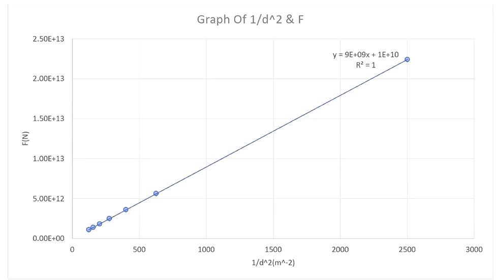
The student wants to know if there is a relationship between diameter of the string and how much force he can hang from the unwound string until it breaks.
State the independent and dependent variable in this experiment
Diameter of the string [2]
Dependent variable: The maximum force the string can withstand before breaking [2]
You are provided with several sets of guitar strings, each with the following diameter.
Diameter of string/mm 0.28
0.33
0.46
0.71
0.97
1.22

The following equipment is also available:
Ruler
Clamp stand Sticky tape Thermometer Stop clock Slotted masses Hanger
Safety glasses Foam mat thread
Strong glue 1 N weights
Design a method to investigate how the force needed to break a guitar string is related to the diameter of the string. In your answer, you should:
Identify two control variables
Length of the guitar string
Material of the string (same type of string, just different diameters)
Select additional equipment you will use
No finger contact involved, so no guitar finger protectors necessary. Micrometer screw gauge to accurately measure the diameter of each string before testing.
Describe how will you set up the equipment
Fix one end of the string to the clamp stand using sticky tape.
Let the string hang vertically with a mass hanger attached to the free end.
Place a foam mat beneath the weights to protect the floor and minimize risk of injury if the weights fall.
Use a ruler to ensure each string is the same length before testing.
Outline how you will collect sufficient data
For each string diameter, I will conduct the experiment at least three times to ensure reliability. I will gradually add 1 N slotted masses to the hanger until the string breaks. I will record the breaking force each time. By repeating the test and calculating the average breaking force for each diameter, I can reduce the impact of anomalies and collect a sufficient set of results for comparison.
Outline how will you make suitable measurements
I will measure the breaking force using 1 N slotted masses, adding them one at a time to the hanger until the string breaks. Each string will be the same length before testing by using a ruler. To confirm the diameter of each string, I will use a micrometer for more precise measurement. I’ll record the exact force at the point of breaking for each trial.
State how you will make sure your method is safe
Wear safety glasses to protect eyes from snapping strings. Stand to the side of the clamp stand and use a foam mat under the weights in case they fall. Check that the clamp stand is stable and on a flat surface before starting.
[18]
[ Total : 22]
4.

Suggest the responsibility of different governments, institutions or companies to minimize the consequences of disasters like Three Mile Island, Fukushima or Chernobyl. In your answer, you should include
· Details of system that should be built into nuclear power plants to reduce the harmful effects of possible nuclear incidents.
Governments, institutions, and companies should work together to build nuclear power plants with robust safety systems such as reactor containment structures to prevent the release of radioactive materials, filtered venting systems to safely release pressure during emergencies, dry cask storage for spent fuel to reduce the risk of leaks, backup power systems to maintain cooling in case of power failure and radiation monitoring and automatic shutdown systems to quickly respond to abnormal conditions.
Institutions like the International Atomic Energy Agency (IAEA) should establish international safety standards and guidelines. Governments should pay for safety systems in power plants. Governments, such as those in the United States and Japan, should fund infrastructure and emergency systems. Companies that build and operate nuclear facilities must follow these regulations and implement the necessary safety technology under government supervision.
[3]
What should be the immediate response after an incident.
The immediate response should center on public safety and containment. Regulatory bodies like the Nuclear Regulatory Commission (NRC) must coordinate with state and local emergency agencies, which can order evacuation of region(s) around the power plant or advise residents to shelter in place for minimizing exposure to radiation. They can also distribute potassium iodide tablets to protect against thyroid cancer. Scientific teams should aptly assess the environmental and health impacts. Authorities must communicate clearly and accurately to avoid public panic and misinformation. Plant operators must promptly cease operations and secure the site immediately.
[3]
How governments and other institutions can plan for long term after an incident.
[4]
The Three Mile Island accident in 1979 led to the formation of an NRC/FEMA joint task force that prepared guidelines assigning onsite emergency planning to nuclear power plant owners, and offsite emergency planning to state and local governments. The NRC reviews onsite emergency procedures and training as part of the plant’s initial licensing process. Plant operators are required to carry out emergency drills with the NRC, FEMA, and local authorities at least once every two years. Offsite emergency response plans are prepared and approved by numerous federal and state authorities, including public health departments and the Department of Homeland Security. This shows that governments, companies, and institutions all share responsibility in managing nuclear safety and response.
[Total :10]
If the magnet is stationary inside or near the coil, the galvanometer shows no deflection and no current is induced. Current is only induced when the magnetic field through the coil is changing. When the north pole of the magnet is pushed into the coil, the galvanometer needle deflects in one direction. This is temporary and solely occurs while the magnet is moving. The rotation was causing a changing magnetic field, and then stops (induced emf stops) and the needle returns to zero. When the magnet is removed out of the coil, the needle deflects in the opposite direction (due to motion), i.e. direction of the induced current has reversed.
If we use the south pole instead, moving it in causes deflection in the opposite direction to the north pole. Moving it out reverses the direction of deflection.
Moving the magnet faster makes the galvanometer deflect more strongly, i.e. the induced emf and current increase with faster changes in magnetic field.
Only when the magnet and coil are in relative motion can a current be produced. This occurs as the magnetic flux through the coil changes. The direction of the induced current depends on the pole of the magnet and the direction of its motion. This is Michael Faraday's electromagnetic induction.
A solenoid with many turns is connected across a sensitive centre-zero millivoltmeter, as shown in Fig. 9.1.

(a) The N pole of a magnet is moved into the solenoid, and then held stationary in the solenoid.
Describe what happens to the needle of the millivoltmeter during this process.
The needle of the millivoltmeter deflects momentarily as the magnet moves into the solenoid, then returns to zero when the magnet is held stationary.
(b) The N pole is then removed from the solenoid. Describe what happens to the needle during this process.
The needle moves/deflects in another direction [1]
(c) Complete the following sentence.
When the N pole moves into the solenoid, electromotive force is induced in the solenoid. [2]
[Total: 5]
Following question is about motion graph. Below is a part of travel graph of Mary’s journey from her house to the shops and back.

a) Find Mary’s speed for the first 30 minutes of her journey. Estimate your answer in km/h. [2]
1 hr = 60 minutes
= 30 minutes
0.5 hours
Speed = Distance / Time
= 20 / 0.5 km/hr
b) Evaluate how much time Mary spends at the shop?
[1]
Given that Mary stops by the shop, from the graph she does so by 30 minutes so she spends 15 minutes in the shop.
45 – 30 = 15 minutes
c) Mary then travels back to her house at 60 km/h. Interpret her journey and Complete the travel graph. [2]
Time = D/S = 20/60 = 1/3 hour = 20 mins
She leaves the shop at 45 minutes, so she returns home at 45+20=65 minutes
Drew a line from (45, 20 km) to (65, 0 km) that slopes downwards, i.e. a return trip at a faster speed (steeper than the first 30 minutes).
----------------------------------------------------------------------------------------------------------------------------------------------------------------------------------------------------------------------


Comments